Project Overview
This website is a description of Sabrina Pereira, Shyheim Russell, and Jonah Spicher's Computer Architecture final project. We pursued this project because we were very enthusiastic on the concept of developing our own music based on the Super Mario Bros. theme.
An 8-Bit Audio Processor
The goals and deliverables of our project
For our project, we dove into developing Verilog representation of a sound controller that allows us to process sounds then produce an 8-bit audio from our hardware. We desired to gain a strong grasp on the functionality and communications of the individual parts of our hardware such as the digital signal processor. For this project, we had three stages:
- MVP: Verilog code of an 8-bit audio hardware with each member having a firm grasp of content
- Planned: Verilog code of the hardware implemented on FPGA ZIBO
- Stretch: Physical hardware implentation on FPGA plugged into a speaker
For this project, what we planned on accomplishing is developing the Verilog code then implement this code on the FPGA through an undetermined manner such that we are able to process the signal. The difference between the stretch and planned goals is that the planned goal does not produce an actual sound through a speaker like in our desired stretch.
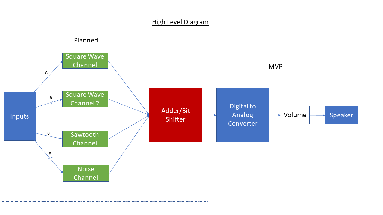
High Level Diagram
Inputs
Our inputs are controlled by notes that are stored in memory and used for generating the wave lengths and frequencies by outputting 18-bit results. Different parts of the result is used to control the different channels turning them on or off.
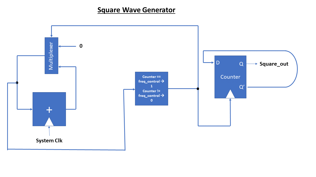
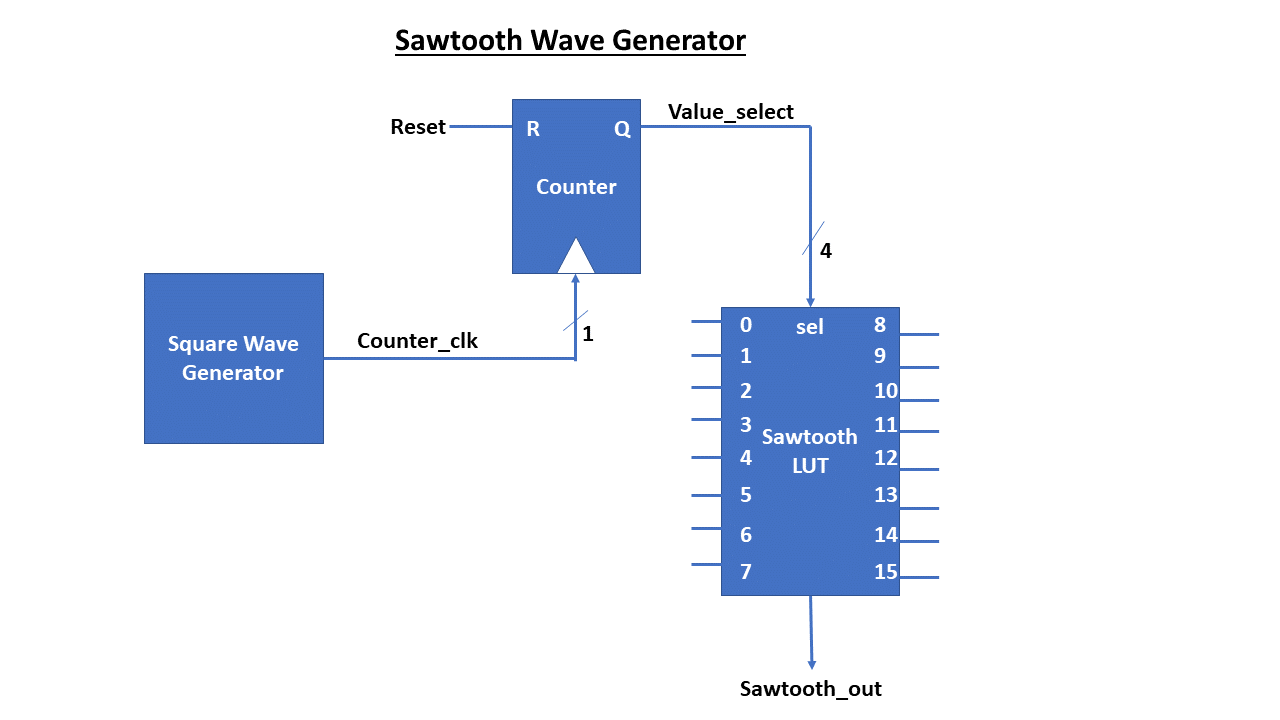
Channels
Our Channels are generate square, sawtooth and noise waves based on the inputs. Each channel is equipped with a wave generator that uses counters to scaffold the frequency and lengths of the waves.
Adder/Bit Shifter
This component was tasked with taking the four channels as input, bit shifting them to the right by 2 arithmetically and output an 8-bit wave from the addition of the four channels using an 8-bit Adder.
Inputs/Channels
For our inputs, we use memory to store the notes that are previously and currently being used, using the next_note as a clock, to then go into memory and output a 18-bit result where the first 8-bit control frequency, the next 8 controls the length of each note, and the final 2 bits control the channel to show which channel is on for this cycle.
From there, the different sections of the output is used in for the four channels through D-Flip-Flops that would AND the channel and frequency where if frequency is low (0), then the channel is also 0, but if frequency is high (1), then the channel would then pass through and allow length to pass through the D-Flip-Flop as well, resulting in the length of time in which each wave generator would be on for.
Adder/Bit Shifter
The Adder takes in uses the four channels as inputs where we take signed 8-bit values from each wave.
The amplitude of each channel are the values are taken into the adder. Channels that are not on have amplitudes and frequencies at zero.
Finally, the signal is normalized then bit shifted by 2 arithmetically, to preserve the sign, then all four values are added to produce an 8-bit sound_ out.
Final Results
The final product and what it does?
For our project, we developed a Verilog representation of the 8-bit hardware that is able to generate 8-bit music using square, sawtooth, and noise channels for different aspects of the song.
We developed a sound card that reads a list of hexadecimal notes (32-bits in binary) and uses those notes to create a sound wave to play. Some examples of the waves it generates are located below. In the end, we were unable to reach our stretch goal of creating a physical hardware implementation on the FPGA, but we were able to produce sound as a whole.
Reflection
Overall, the teaming experience and collaboration worked well as each member was able to contribute and grow through taking point on different aspects of the project. For example:
To discuss our final system, it operates as desired as each component works together to output the results we expect. We were not able to implement goals that allowed us to dig deeper into the development of the physical sound hardware, but the Verilog simulation works as expected. It does not normalize volume as intelligently as we desired or implement it on FPGA, but it does have four channels that generate one wave each at a given frequency for its type. The frequency is controlled by input controlls that reads from memory and uses memory to iterate through what notes to play next. Finally, through a Python script, we compile the notes to create a .wav file to play the music.
How to Run
Sound Files
Here are some of the sound files we were able to develop:
References
Here is a list of references and resources we used for inspiration:
- Harmonia. “Digital Audio: the Real Meaning of 8-Bit Music.” Medium, Medium, 21 Aug. 2019, medium.com/@harmonia.global/digital-audio-the-real-meaning-of-8-bit-music-1be5fc8ab2b1.
- The 8-Bit Guy, director. How Oldschool Sound/Music Worked. Youtube, 5 Oct. 2015, www.youtube.com/watch?v=q_3d1x2VPxk.
- Suits, B. H. “Physics of Music - Notes.” Frequencies of Musical Notes, A4 = 440 Hz, pages.mtu.edu/~suits/notefreqs.html.
Our Team
The team of students engineers who worked on this project.

Jonah Spicher
Junior, ECE
Sabrina Pereira
Junior, ECE